Tonewheels Electronics
INTRODUCTION
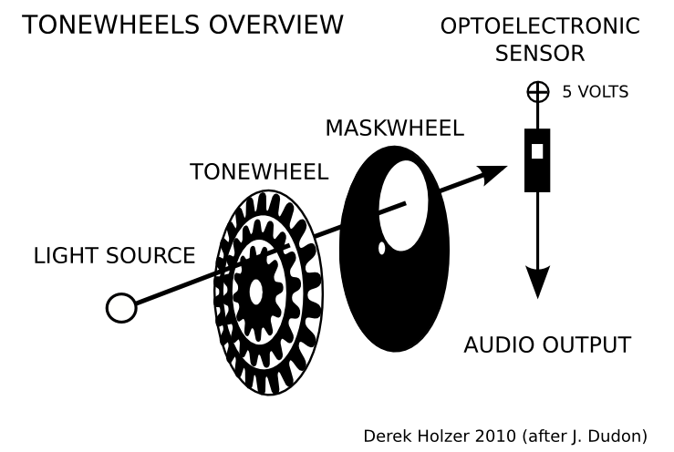
The astonishingly simple technology employed by the TONEWHEELS project creates sound directly from light by means of an optoelectronic sensor. In the diagram above, a LIGHT SOURCE is directed through two transparent, spinning disks. The first disk, the TONEWHEEL, has patterns representing sound waves printed on it. This disk modulates the light in a similar manner as the optical soundtrack of 16mm and 35mm motion picture film. The tone produced depends on both the number of peaks printed on the disk, and the speed at which the disk rotates.
After the first TONEWHEEL, any number of secondary MASKWHEELS may be used to further filter or modulate the light before it reaches the sensor. These MASKWHEELS create the same kind of amplitude modulation as the low-frequency oscillators in analog synthesizers, and are heard as anything from a rhythmic pulse to additional sonic frequencies.
Once the light has passed through these various wheels, it falls on the OPTOELECTRONIC SENSOR, typically a phototransistor or photodiode. This sensor allows five volts of direct electrical current to pass through when exposed to light, and blocks the current when in shadow. From there, the modulated current may be used as an audio signal by connecting the AUDIO OUTPUT to an amplifier and speaker, or it may be sent through a mixer and various other electronic effects for further treatment.
LIGHT SENSOR ELECTRONICS
In order to connect an optoelectronic sensor to many types of audio equipment (mixer inputs, guitar effects, modular synthesizers, etc etc), it is necessary to create an output buffer. Buffers are simple circuits, often using one or more op-amps, which act as the middle-man and help other circuits talk to each other in the the world of electronics.
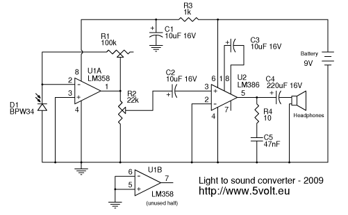
The light to sound converter circuit above was designed by Alex at 5volt.eu. It uses a BPW34 photodiode instead of a phototransistor, and the diode makes a connection to ground rather than to power. That is followed by U1, which uses an LM358 op-amp chip as the buffer. The op-amp is configured as an inverting op-amp, which means it will give positive voltage at the output (pin 1) when it sees a connection to ground at the inverting input (pin 2).
R1 is a potentiometer, which controls the threshold of the op-amp. This means that you can adjust the circuit to the contrast between light and shadow in order to give the strongest signal out. R2 is another potentiometer, which controls the output volume, and C2 is a capacitor which blocks any DC voltage (the constant part of the signal, rather than the part which is AC–the audio part) from going further in the circuit. If you plan to connect this circuit to a mixer, then an output jack can be inserted between C2 and pin 3 of U2, the LM386 amplifier.
I have designed a Printed Circuit Board for this circuit with an added output jack for connecting to a mixer. R4 and C5 have been omitted from my design:

Here is the parts overlay for the project (enlarged from PCB for clarity, click for full size):

And here is a photo of the completed project:

MOTOR ELECTRONICS
In order to control the speed of the motor which spins the TONEWHEEL in front of the optoelectronic sensor, you can use this Pulse Width Modulation Motor Speed Controller. The circuit is based on the commonly-available 555 timer Integrated Circuit. It should work with Direct Current motors up to 1 or even 1.5 Amps, and has a wide range of control over nearly the entire rotation of the potentiometer. Almost any pot from 25K – 250K could be used in place of the 100K I specify in the parts overlay below.

It is not recommended to use the same power supply for the motors and the light-to-sound converter, as the motor controller produces a lot of electromagnetic noise. I have also designed a PCB and parts overlay for this motor controller:


More information about the TONEWHEELS project can be found on the Tonewheels Performance and Tonewheels Workshop pages. To see all blog posts related to TONEWHEELS, click here.