8 Bit Mix Tape Tutorial
8-Bit SoundBox from macumbista on Vimeo.
INTRODUCTION
This tutorial aims to give instructions on how to build and program the 8BitMixTape project from start to finish.
Since 2013, an international team of geeks from Lifepatch.org (Indonesia) and various groups in Switzerland [dusjagr labs, SGMK, a.n.y.m.a, Gaudi Labs, and StahlNOW] have developed a series of 8bit MixTapes, sound-codes and homemade circuit boards.
The 8bit MixTape is a very simple sounds & beats generator based on an ATtiny microcontroller, compatible with and programmable using the popular Arduino environment. Only a little bit of soldering is needed and you then can start programming your own sounds, noises and 8bit tunes. Generating a sound on an 8bit chip like the ATtiny is very easy. You can start with simple square waves, and later on go to more interesting algorithmic sounds using the famous one-liners introduced in the demo-scene by viznut.
SRC: http://wiki.sgmk-ssam.ch/wiki/FabLab_Neckar-Alb_-_8bit_MixTape_Workshop
MAIN LINKS
http://wiki.sgmk-ssam.ch/wiki/8bit_Mix_Tape
https://github.com/8BitMixtape
http://lifepatch.org/8-bit_Mixtape [INDONESIAN]
http://countercomplex.blogspot.com/2011/10/algorithmic-symphonies-from-one-line-of.html
HARDWARE
1) WIRING DIAGRAM
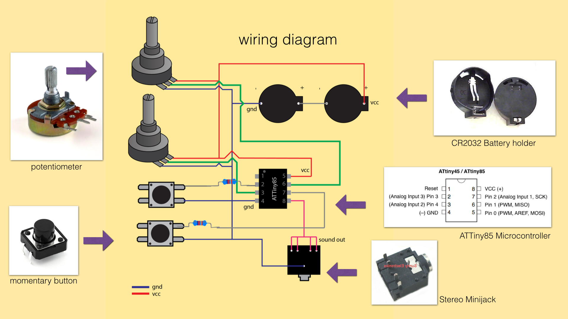
Pay attention to the colors to see where things go! (Blue = GND, for example…)
SRC: http://lifepatch.org/File:8-bit_Mixtape_Wiring_Diagram.jpg
2) PARTSLIST
The following parts are necessary to build an 8BitMixTape on your own:
1 x ATMEL ATtiny85 microcontroller IC (DIP8 package)
2 x Potentiometer (linear, 10K or 100K ?)
2 x Momentary push switch
2 x 10K resistor
2 x CR2032 3V battery
2 x CR2032 battery holder
1 x 6 pin female header (0.1″/2.54mm spacing)
1 x Female minijack audio connector
1 x breadboard or prototyping stip/dot board
Hookup wire
3) WHAT ELSE YOU WILL NEED
For this tutorial, you will need the following:
1) One 8BitMixTape PCB (or similar self-made ATtiny85 microcontroller project, see schematic above)
2) One Arduino Uno, Duemilanove, or newer board (the UNO will be used in this tutorial)
3) One 10uF electrolytic capacitor
4) One connector cable, made of 6 wires with a row of 6 male header pins on each end (0.1″/2.54mm spacing). Alternately, you could simply use solid core jumper wire for the connections.
5) One USB-A to USB-B cable (to connect the Arduino to your computer)
6) Arduino 1.6.8 installed on your computer
7) A way to listen to the output: external powered speaker or headphone amp + headphones (the 8BitMixTape shouldn’t be connected directly to the headphones or speakers) plus a minijack cable to connect your 8BitMixTape to the listening hardware.
8) OPTIONAL: One USB-A to micro-USB cable (to connect power to your 8BitMixTape if it has USB power connector)
9) OPTIONAL: two cr2302 batteries to power your 8BitMixTape if the board has battery connectors
GETTING STARTED
1) SETTING UP ARDUINO as IN-SYSTEM PROCESSOR
If your 8BitMixTape doesn’t have any code loaded onto it yet, you will first need to add a bootloader to it and then program it with your Arduino code.
The micro-USB connector (if present) on your 8BitMixTape is for *power only*, so we will need to use an Arduino board (the UNO will be used in this tutorial) to program the 8BitMixTape.
First, we’ll need to turn the Arduino board into an “in-system programmer” (ISP). To do this, follow these instructions:
	Run the Arduino development environment.

	Under TOOLS, select the correct board and port.

	Also under TOOLS, make sure PROGRAMMER is set to AVR ISP.

	Open the ArduinoISP sketch from
		FILES->EXAMPLES->11.ARDUINOISP->ARDUINOISP

	In the ArduinoISP sketch, uncomment the following line:
		#define USE_OLD_STYLE_WIRING

	Upload the ArduinoISP sketch to your Arduino board.
REF: http://highlowtech.org/?p=1706
2) CONNECTING THE 8BitMixTape TO THE ARDUINO
Next we need to make the proper connections between the Arduino and the 8BitMixTape. On the back side of the 8BitMixTape is a female header with 6 connections:
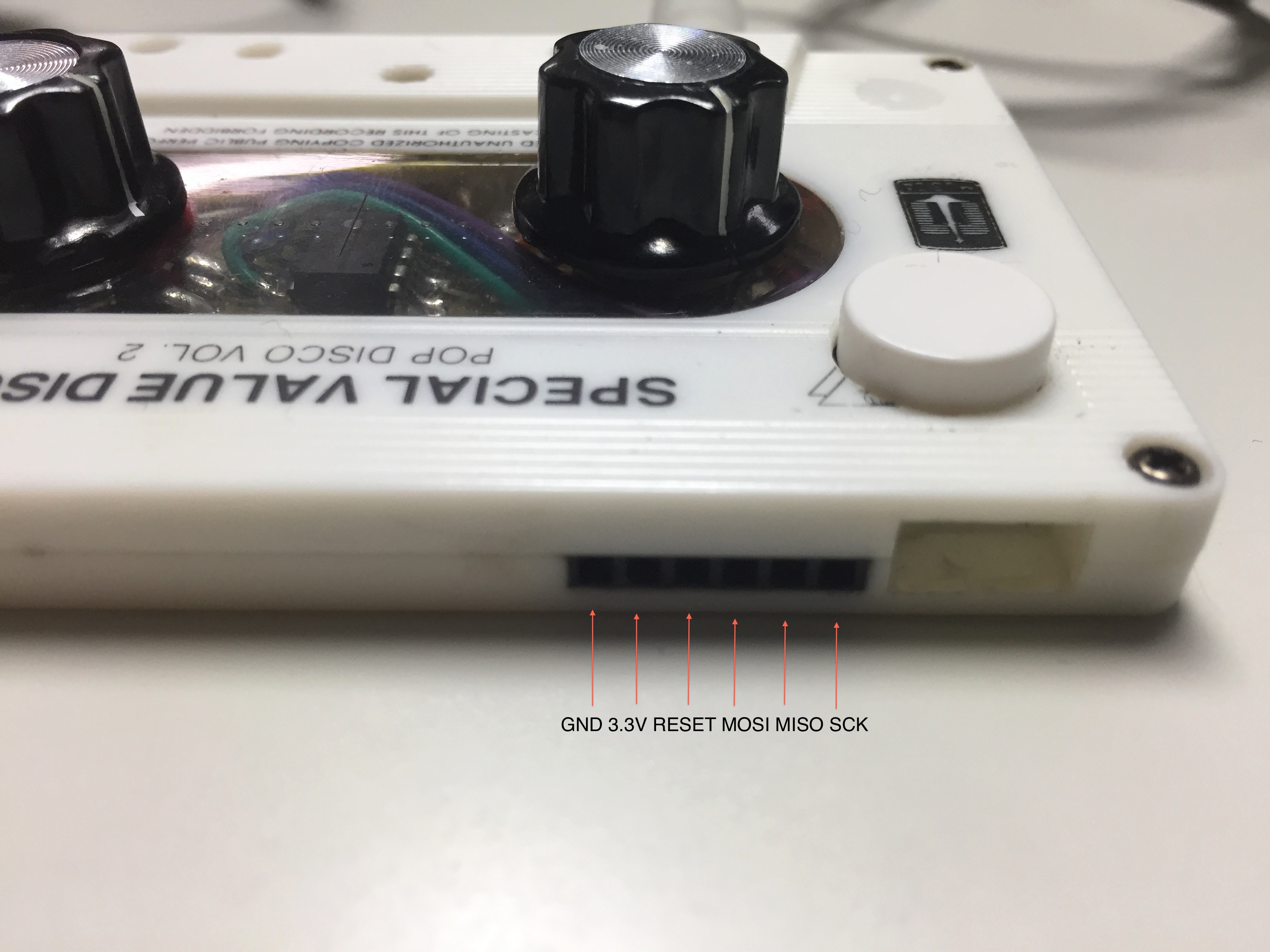
Which are named in the following order (left-to-right):
GND VCC RESET MOSI MISO SCK
(NOTE: if you are building your own 8BitMixTape from scratch, these header pins are connected directly to the corresponding pins on the ATtiny, and are not shown explicitly in the schematic at the start of this tutorial, but can be inferred from the IC pin names in that drawing.)
I recommend soldering up a cable like this:
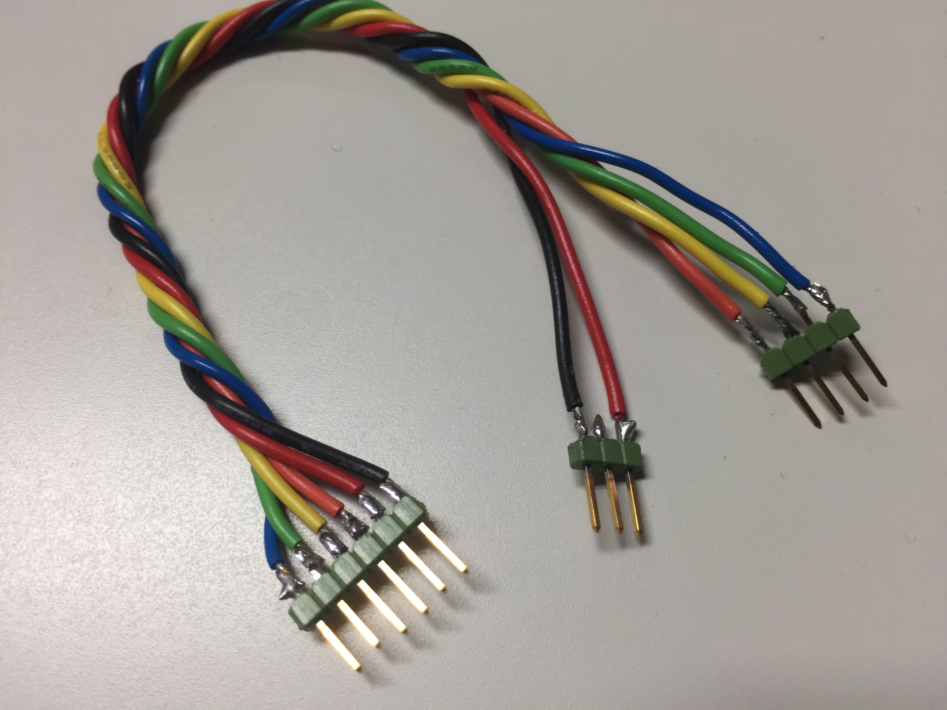
And using it to connect the 8BitMixTape to your Arduino as follows:
[8BitMixTape FEMALE HEADER on this end]

GND   VCC   RESET   MOSI   MISO    SCK
 |     |      |      |       |      |
Black Red  Orange  Yellow  Green  Blue
 |     |      |      |       |      |
GND   3.3V  pin10  pin11   pin12  pin13

[ARDUINO UNO PINS on this end]
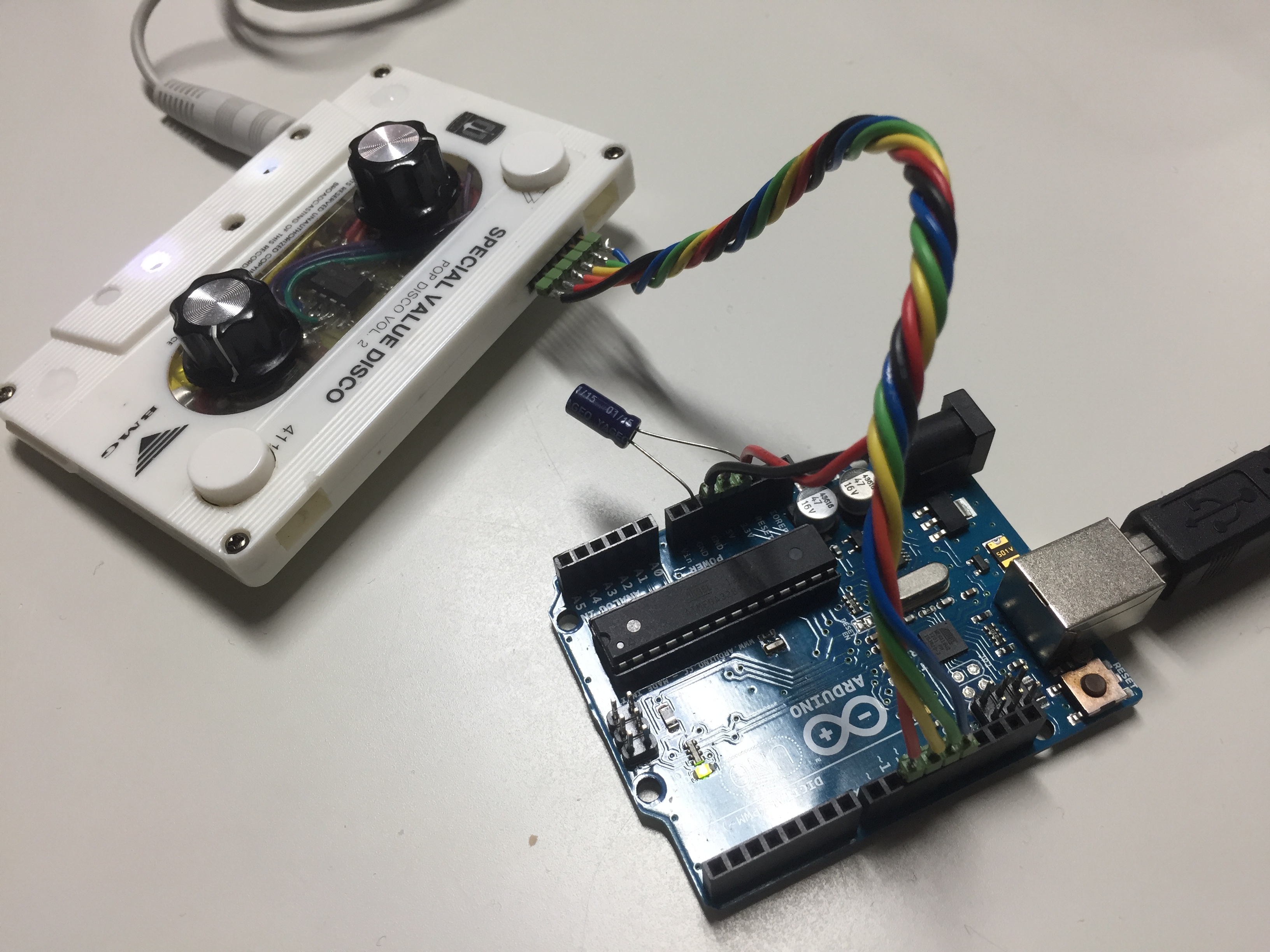
Additionally, you will need to put the 10uF capacitor on the Arduino board, with the + leg in the Arduino pin labelled RESET and the – leg in the Arduino pin labelled GND.
It will then look like this:
Which is the functional equivalent of this:
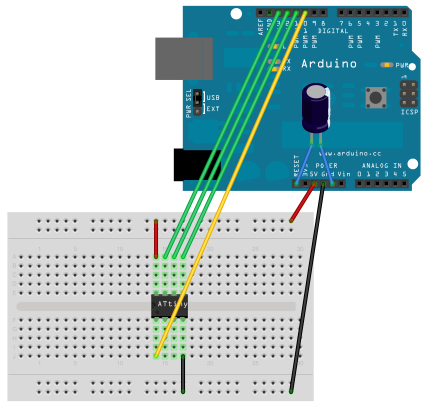
SRC: http://highlowtech.org/?p=1695
Note that the 8BitMixTape can be powered in this way as well, without the micro-USB cable or batteries. I recommend disconnecting the micro-USB cable or batteries (if present) from the 8BitMixTape while programming it and taking the power from the header cable you have created instead. This way the second power supply doesn’t flow “backwards” into your Arduino!
3) LOADING THE 8BitMixTape BOOTLOADER
The bootloader is a piece of code which runs when the ATtiny processor starts up, and allows you to use the Arduino program to load your own code onto the chip. So our next step is to add support for the 8BitMixTape to our Arduino application. To do this download and unzip the following:
https://github.com/8BitMixtape/8Step-MixTape-Berliner-Schule/archive/master.zip
Inside this archive, locate the following folder:
8Step-MixTape-Berliner-Schule-master->arduino_hardware->hardware->8BitMixtape
And copy that “8BitMixtape” folder to the following location (on MacOS you must CMD+click to “Show Package Contents”, TODO = location on other platforms):
Arduino.app->Contents->Java->hardware
Restart your Arduino application and under the TOOLS->BOARD menu you should now see “8BitMixtTape”.
Set up your ARDUINO as follows under the TOOLS menu:
	BOARD = 8BitMixtTape
	PROCESSOR = 8Bit-ATtiny85
	CLOCK = 8 MHz (internal)
	PORT = your Arduino port
	PROGRAMMER = Arduino as ISP
Now click “Burn Bootloader” under the TOOLS menu and wait for confirmation that the bootloader has been sent to the 8BitMixTape.
4) LOADING YOUR ARDUINO CODE TO THE 8BitMixTape
Now you are ready to rock your own code on the 8BitMixTape! To start with, copy the following code into your Arduino program. In this code, the right-hand button switches between 8 different algorithmic, interactive compositions, and the two potentiometers change different parameters within them.
//////BEGIN EXAMPLE CODE//////

/* PCrazy shit 8-bit symphony generator */
/*     */

/*
 * inspired by:
 *  http://countercomplex.blogspot.com/2011/10/algorithmic-symphonies-from-one-line-of.html
 */

// ATMEL ATTINY85 / ARDUINO
//
//                      +-\/-+
//  Reset A0 (D 5) PB5 1|    |8  Vcc
//        A3 (D 3) PB3 2|    |7  PB2 (D 2) A1
//   A2 pwm4 (D 4) PB4 3|    |6  PB1 (D 1) pwm1
//                 GND 4|    |5  PB0 (D 0) pwm0
//                      +----+


int speakerPin = PB0;
int buttonPin = PB1;
int potiPin3 = A2;
int potiPin4 = A1;

int buttonState = 0;
int lastButtonState = 0;
int count = -1;

unsigned long int pulseWidthOFF = 0;
unsigned long int pulseWidthON = 0;
unsigned long int pulseWidthPart = 0;

     unsigned long int newr;
     unsigned char lobit;
     unsigned char b31, b29, b25, b24;

int samplingDelay;
unsigned long int reg;

long t = 0;
int v = 0;
unsigned int c3 = 0;
unsigned int c4 = 4;

unsigned int analogValue;

void setup () {
  //TCCR0A |= (1<<WGM00)|(1<<WGM01); //Fast pwm
  TCCR0B = TCCR0B & 0b11111001; //no timer pre-scaler, fast PWM

    pinMode (speakerPin, OUTPUT);
    pinMode(buttonPin, INPUT);
    digitalWrite(buttonPin, HIGH);
    pinMode (potiPin3, INPUT);
    pinMode (potiPin4, INPUT);

    reg = 0x551155aaL;

}

void loop () {
  // read the state of the switch into a local variable:
  buttonState = digitalRead(buttonPin);

  if (buttonState != lastButtonState && buttonState == HIGH) {
     // if the state has changed, increment the counter
       count++;
       t = 0;
        delay(10000);
        if (count > 9) {
        count = 0;
      }

  }

  lastButtonState = buttonState;


 //count = 2;

 switch(count) {

 case 0: // a classic

     c4 = ((analogRead(potiPin4)>>6) + 1);
     c3 = (analogRead(potiPin3)>>0);
     v = (t*(t>>8|t>>4))>>(t>>c4);
    analogWrite (speakerPin, v);

    delayMicroseconds(c3>>2);
    t++;

    break;

 case 1: // ding dong

     c4 = ((1023-(analogRead(potiPin4))>>6) + 1);
     c3 = (analogRead(potiPin3)>>0);
     v = t * ((t>>15|t>>c4)&83&t>>(c4>>3));
     analogWrite (speakerPin, v);

     delayMicroseconds(c3<<2);
      t++;

       break;

  case 2: // experimental 8 bit

     c4 = ((analogRead(potiPin4)>>6) + 1);
     c3 = (analogRead(potiPin3)>>0);
     v = t * ((t>>15|t>>c4)&83&t>>(c4>>3));
     analogWrite (speakerPin, v);
     delayMicroseconds(c3<<3);
     t++;
        break;

  case 3:

     c4 = ((analogRead(potiPin4)>>2) + 1);
     c3 = (analogRead(potiPin3)>>0);


     b31 = (reg & (1L << 31)) >> 31;
     b29 = (reg & (1L << 29)) >> 29;
     b25 = (reg & (1L << 25)) >> 25;
     b24 = (reg & (1L << 24)) >> 24;

    lobit = b31 ^ b29 ^ b25 ^ b24;

      newr = (reg << 1) | lobit;

      reg = newr;

    v = t * ((t>>c4|t>>reg)&7&t>>3);


  //v = t * ((t>>4|t>>7)&c4&t>>(reg));
  //v = t * ((t>>c4|t>>reg)&7&t>>3);


  digitalWrite (speakerPin, v);
  delayMicroseconds(c3>>0);
  t++;


     break;

 case 4:

    c4 = ((analogRead(potiPin4)>>2) + 1);
    c3 = (analogRead(potiPin3)>>0);


  v = (t|3) * ((t>>1|t>>6)&c4&t>>3);


  //v = t * ((t>>4|t>>7)&c4&t>>(reg));
  //v = t * ((t>>c4|t>>reg)&7&t>>3);


  analogWrite (speakerPin, v);
  delayMicroseconds(c3>>0);
  t++;


    break;

 case 5:

    c4 = ((analogRead(potiPin4)>>6) + 1);
    c3 = analogRead(potiPin3);

  v = t>>4&1?t>>5:-t>>c4 ;

  analogWrite (speakerPin, v);
  delayMicroseconds(c3>>1);
  t++;


    break;

 case 6:

    c4 = ((1023-(analogRead(potiPin4))>>6) + 1);
    c3 = (analogRead(potiPin3)>>0);

   //v = (t|3) * ((t>>2|t>>83)&13&t>>c4);
   v = (t|c4) * ((t>>c4|t>>11)&47&t>>3);

  //v = t * ((t>>4|t>>7)&c4&t>>(reg));
  //v = t * ((t>>c4|t>>reg)&7&t>>3);
  //v = (1 & 17) * (t|83) * ((t>>c4|t>>17)&7&t>>3);


  analogWrite (speakerPin, v);
  delayMicroseconds(c3>>2);
  t++;


    break;

 case 7:

    c4 = ((1023-(analogRead(potiPin4))>>8) + 1);
    c3 = (analogRead(potiPin3)>>0);

   //v = (t|3) * ((t>>2|t>>83)&13&t>>c4);
   v = t * ((t>>c4|t>>3)&17&t>>9);

  //v = t * ((t>>4|t>>7)&c4&t>>(reg));
  //v = t * ((t>>c4|t>>reg)&7&t>>3);
  //v = (1 & 17) * (t|83) * ((t>>c4|t>>17)&7&t>>3);


  digitalWrite (speakerPin, v);
  delayMicroseconds(c3>>2);
  t++;


    break;

 case 8:

    c4 = ((analogRead(potiPin4)>>2) + 1);
    c3 = (analogRead(potiPin3)>>0);


  v = t * ((t>>c4|t>>83)&7&t>>5);


  digitalWrite (speakerPin, v);
  delayMicroseconds(c3>>0);
  t++;


    break;
 }

}


//////END EXAMPLE CODE//////
SRC: https://github.com/8BitMixtape
Lines that look like this:
v = (t*(t>>8|t>>4))>>(t>>c4);
are the “one-liner” algorithmic compositions, which use different bit shifting and mathematical operations from C code to generate “audio” (i.e. a series of bits) sent to the PWM output pin of the ATtiny as variable “v”.
Anything marked “c3” or “c4” is where the potentiometers affect the running code. The “c3” potentiometer usually controls the speed of how quickly the algorithm repeats itself, while the “c4” potentiometer introduces different amounts of bitshifting into the running code.
You can try replacing the one-liner with some of the commented-out lines instead for different versions.
To skip to a certain composition on startup, uncomment the line:
//count = 2;
and replace the number with the case number of the composition you want to start with. The button will still move forward if you press it running this code.
At this point you may want to read the blog posts which started all this:
http://countercomplex.blogspot.fi/2011/10/algorithmic-symphonies-from-one-line-of.html
http://countercomplex.blogspot.fi/2011/10/some-deep-analysis-of-one-line-music.html
Or you may want to try other one-liners such as these:
http://macumbista.net/wp-content/uploads/2016/11/music_formula_collection.txt
Or you may just want to start experimenting by replacing the numbers and bitwise operations (“>>” and “<<“) with other values and directions, by replacing the fixed values in the code with variables from the potentiometers (“c3” and “c4”), or by adding additional math operations (+, -, *, /, ^, &, %, pi, sin, tan, sqrt, etc etc…) to any of the fixed values or variables.
A great many of the one-liners found in the text file linked were “discovered” accidentally through trial-and-error, rather than by design with an outcome in mind from the start. So go crazy!
One-liners with no externally-dependent variables (i.e. the potentiometer values) can be previewed here:
http://wurstcaptures.untergrund.net/music/
5) FINAL HARDWARE NOTES
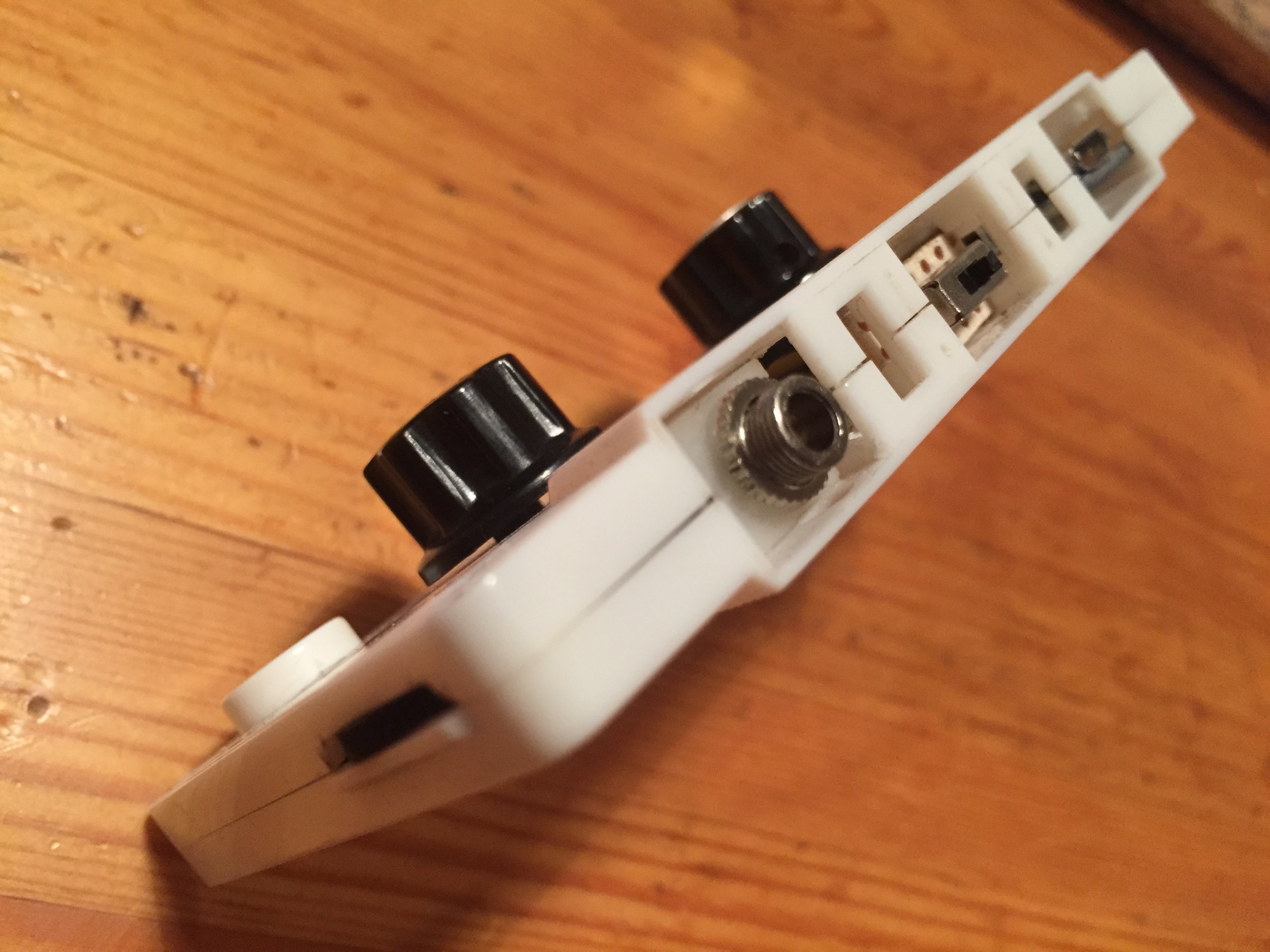
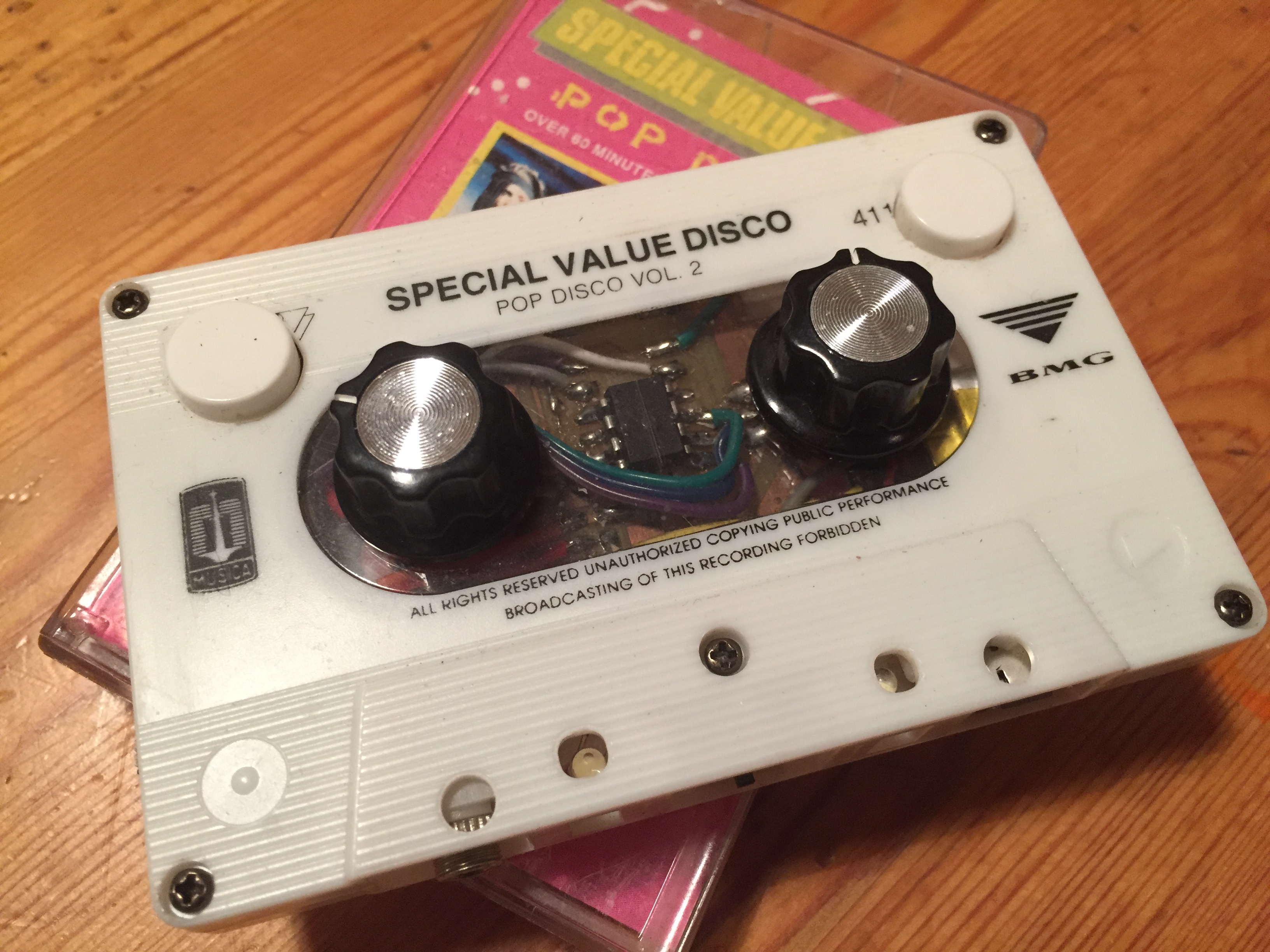
There are already a great many hardware versions of the 8BitMixTape. Mine was sent to me by Andreas Siagian of Lifepatch.org. It has a micro-USB connection for charging an internal battery (not sure if mine is working yet) and a snappy cassette-tape enclosure!
Other 8BitMixTapes have built-in batteries for powering.
The switch in the middle of the bottom side of the cassette turns the unit ON (right hand position) and OFF (left hand position). It should be in the OFF position to charge, and the red LED on the charger PCB (behind the min USB connection) turns blue when charged. The charge should last about an hour.
I absolutely DO NOT recommend listening to the 8BitMixTape when the micro-USB cable is connected, as the USB power and circuitry for charging the battery create a lot of extra noise. Also, be careful not to connect the micro-USB power cable when the 8BitMixTape is connected to the 3.3V pin of the Arduino, as the USB power can flow “backwards” into the Arduino 3.3V and mess things up in the Arduino. Another solution could be to not include the 3.3V in your header cable, and use the USB or battery power instead while programming the 8BitMixTape.
I also recommend disconnecting the programming header pins from the Arduino when running the 8BitMixTape. You will see that I separated the two parts of the header cable to allow the power to remain connected when the programming pins are disconnected.
Have fun and many thanks to Andreas Siagian and Marc “Dusjagr” Dusseiller for their time and help making this tutorial.
Derek Holzer
Helsinki
27 OCT 2016