Analog Multiplier Module
Overview
This synthesizer module allows “Buchlidian” style processing of three input voltages. It can do much of what the original Buchla 257 Voltage Processor does: addition, subtraction, multiplication and division. The only feature of the 257 it lacks is the ability to “transfer control” (i.e. interpolate) between the two different applied voltages
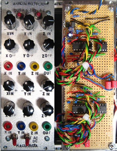
It contains one section with three attenuverting/bipolar inputs, which allow the user to sweep between the original signal on the right hand side of the potentiometer and an inverted version of the signal on the left hand side, with no signal passing through at the middle position. An offset control is also present to add a fixed DC voltage to the signal.
The other section contains an analog multiplier with three inputs, X, Y and Z, each hardwired to one of the attenuverting outputs. Output is calculated as follows:
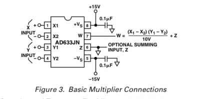
W out = ((X1 – X2)(Y1 – Y2)) / 10V + Z
The panel contains two of each section. The X and Y inputs can be switched between AC and DC coupling, with an AC breakpoint of approximately 0.2 Hz, while the Z input is always DC coupled.
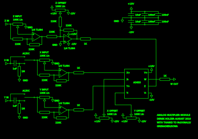
Schematic
Tom Bugs described himself as a magpie to me once in regards to his circuit designs, and while working on this module I have followed his lead. The “attenuverter” sections were designed by Chris MacDonald and modified by Peter Grenader, and have been further developed by Matthias Herrmann/Fonitronik.
Likewise the analog multiplier section is really just bringing every feature of the AD633 4 quadrant multiplier chip to the front panel, with some inspiration from Roman Sowa’s Ring Modulator design, as well as Marc Bareille’s adaption of that same design.
[click schematic to enlarge]
Usage
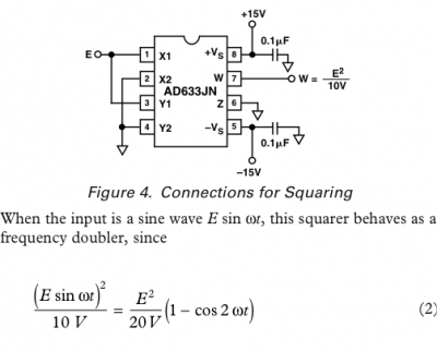
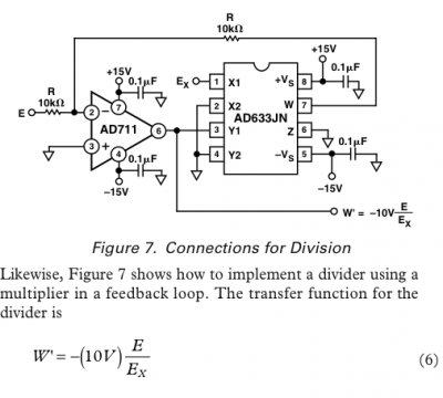
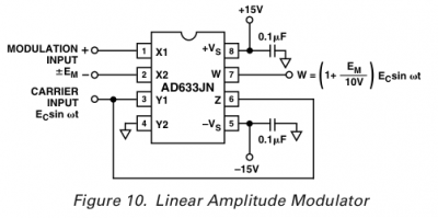
The AD633 documentation shows different applications such as simple multiplication, squaring and division as well as more complex tasks such as a linear Voltage Controlled Amplifier as well as 6dB/Octave Voltage Controlled Filters and a Quadrature Oscillator (both not shown here). The most common sonic use of this IC is for ring modulator circuits.
However, my main application for this is the creation of different kinds of transfer functions for use in chaotic synthesis. I discovered how useful the analog multiplier is while experimenting with the Doepfer system at KHM in Cologne. Multiplying two oscillators through a ring modulator, sending the result to modulate the first oscillator and using the first to modulate the second created an amazing array of unpredictable but certainly far from random results.
In most applications shown in the datasheet, the X and Y offset pins are grounded. But while breadboarding, I discovered that the X and Y offset gave a higher level of control over the modulations, so I built them into the panel. Likewise, switching between AC and DC coupling alters the resulting sound immensely, with the best results coming from one signal being AC coupled and one being DC coupled.
Adding one of the X or Y input signals to the Z input creates a kind of VCA which strengthens the effect. Or using another signal, such as a Low Frequency Oscillator with some suitable gain and offset, adds another modulation source into the mix to provide anything from amplitude modulation to clipping.
I believe this module gets at just about any type of processing the AD633 can do, as most of the time there is no attenuation, inversion, Z input or any kind of offset available on a normal ring modulator or analog multiplier.
[…] case with 2 x Thomas Henry VCOs, one CGS Digital Noise, one Serge Smooth/Stepped Generator and 2 x Analog Multipliers, as well as two built-in, padded line-outs and a new LED lightbar mount. The first test-patch I […]